Content
- 1 What Makes LSR Injection Molding Fundamentally Different
- 2 Core Components of an LSR Injection Molding Machine
- 3 Mold Design Principles Specific to LSR Processing
- 4 Key Process Parameters and Their Effect on Part Quality
- 5 Designing LSR Parts for Moldability and Performance
- 6 Common Defects in LSR Molding and Their Root Causes
What Makes LSR Injection Molding Fundamentally Different
Liquid silicone rubber (LSR) injection molding is a precision manufacturing process that differs from conventional thermoplastic injection molding in nearly every critical parameter. Where thermoplastic molding injects a heated material into a cooled mold to solidify, LSR molding does the opposite: a cold, two-component liquid silicone compound is injected into a heated mold where it undergoes an addition-cure crosslinking reaction and permanently vulcanizes into a flexible, durable elastomeric part. This thermal inversion—cold injection into a hot mold—defines the entire machine architecture, mold design philosophy, and process control strategy required for successful LSR production. Understanding this fundamental reversal is the starting point for anyone specifying, operating, or designing around an LSR injection molding machine.
LSR compounds are supplied as two-part systems: Part A contains the base polymer with a platinum catalyst, and Part B contains the crosslinker and inhibitor package. These two components are stored separately to prevent premature cure, metered in a 1:1 ratio by the machine's dosing system, blended in a static mixer immediately before injection, and delivered to the mold in a thermally conditioned, highly controlled flow. The entire material handling and injection system must be maintained at temperatures between 5°C and 25°C to prevent premature gelation, while the mold simultaneously operates at 150°C to 220°C to drive rapid full cure. Managing this thermal contrast throughout the machine and mold is the central engineering challenge of LSR injection molding.
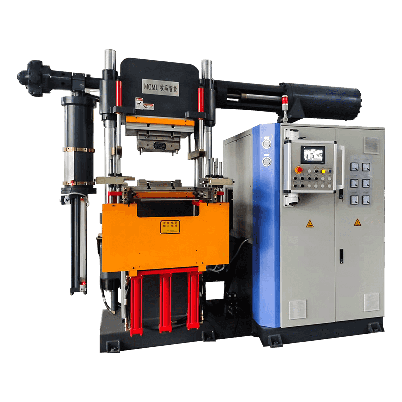
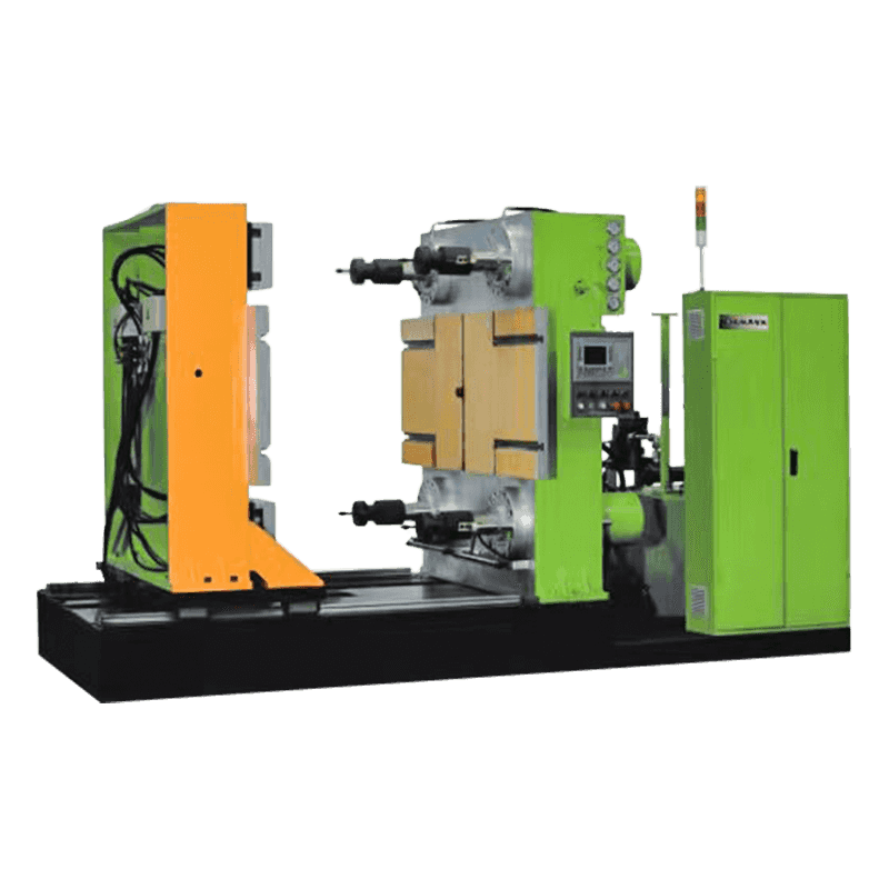
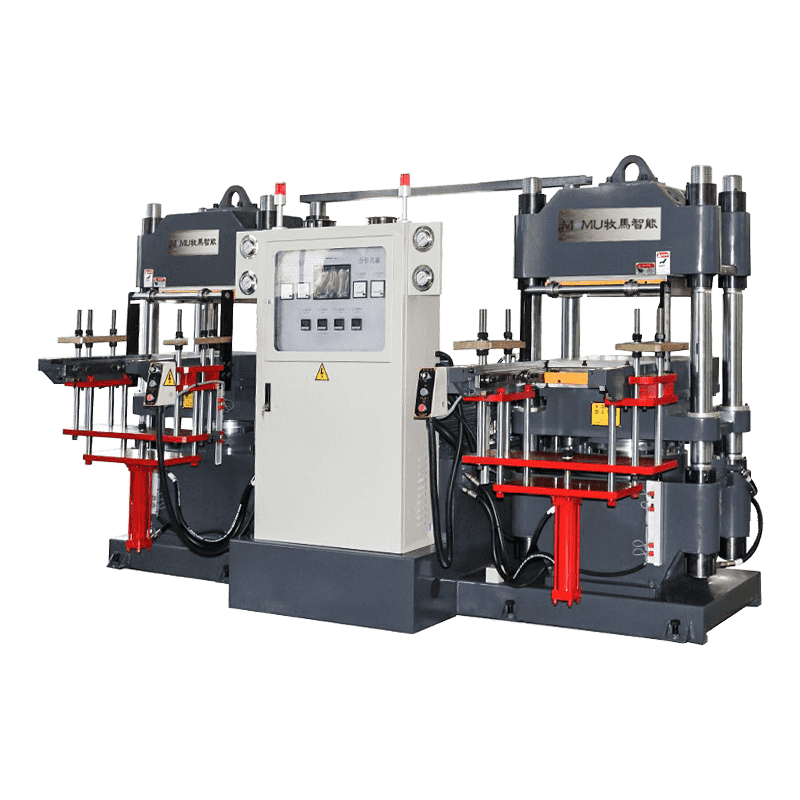
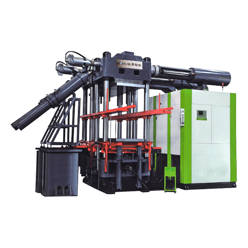
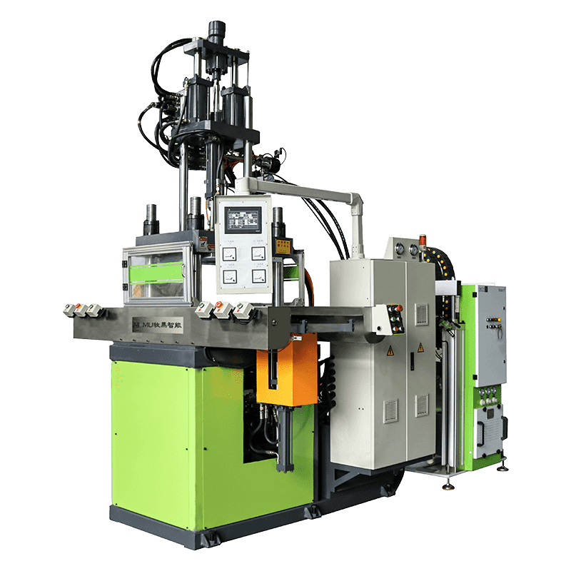
Core Components of an LSR Injection Molding Machine
An LSR injection molding machine is an integrated system comprising several subsystems that must work in precise coordination to deliver consistent part quality. Unlike a standard thermoplastic injection machine where the barrel and screw perform plasticization and injection, the LSR machine's injection unit is purpose-built for handling a low-viscosity, thermally sensitive two-component liquid. Each subsystem plays a specific and non-substitutable role in the process.
Two-Component Metering and Dosing System
The metering system draws Part A and Part B from supply drums or pails using follower plates that maintain constant pressure on the material surface and prevent air entrainment. Precision gear pumps or piston-type metering pumps deliver both components simultaneously at a precisely controlled 1:1 volumetric ratio, with ratio accuracy typically held within ±1% to ensure consistent crosslink density and final hardness. Many systems also incorporate a pigment dosing line—a third metering stream that introduces color masterbatch or functional additives into the mixing head at programmable ratios, enabling multi-color or additive-dosed production without manual compound preparation. Pressure sensors and flow meters throughout the dosing circuit provide real-time feedback that triggers alarms and machine stops if ratio drift or flow anomalies are detected.
Static Mixing and Cold Runner System
After metering, the two components pass through a disposable static mixer—a tube containing a series of helical mixing elements that progressively divide and recombine the material streams until complete homogeneous blending is achieved, typically within 20 to 40 mixing elements depending on compound viscosity and desired mix quality. The mixed compound then enters the cold runner system in the mold, which is a thermally isolated manifold maintained at the same cool temperature as the injection barrel—typically below 20°C—using water cooling circuits that run independently of the hot mold temperature control. The cold runner retains un-cured LSR between shots, preventing material waste and enabling automatic de-gating since the cold runner sprue and runners remain liquid and are retracted with the opening of the mold, leaving no cured runner scrap to trim or recycle.
Injection Barrel and Reciprocating Screw
The injection barrel receives the mixed LSR compound from the cold runner manifold and uses a low-compression reciprocating screw to accumulate a shot of material and inject it into the mold cavities. Unlike thermoplastic screws, which are designed to generate heat through shear, LSR injection screws have very low compression ratios (typically 1:1 to 1.2:1) and are designed to convey material with minimal shear heating to avoid triggering premature cure in the barrel. The entire barrel assembly is jacketed with water cooling to maintain the material temperature below the activation threshold of the platinum catalyst. Shot size accuracy is critical in LSR molding because the material has very low viscosity and will flash across even small gaps if the shot volume exceeds cavity volume—typical injection pressure for LSR ranges from 100 to 250 bar, considerably lower than thermoplastic injection pressures.
Mold Design Principles Specific to LSR Processing
LSR mold design follows principles that are in many respects the inverse of thermoplastic mold design. Because LSR shrinks slightly on cure (typically 2–4% linear shrinkage depending on compound and cure conditions) and has extremely low viscosity in its uncured state, the mold must be designed with tighter parting line tolerances, more aggressive venting strategies, and a thermal architecture that promotes rapid and uniform cure throughout the cavity. Mold construction typically uses hardened tool steel at P20 or H13 grade, with cavity surfaces polished to Ra 0.05 µm or better to achieve the required surface finish on medical, optical, or consumer-grade LSR parts.
Parting Line Tolerances and Flash Prevention
The low viscosity of LSR—typically 50,000 to 300,000 mPa·s at injection temperature—means it will penetrate gaps as small as 0.004 mm at injection pressure, producing flash that is extremely thin, difficult to trim, and unacceptable in precision applications. Parting line surfaces must be ground flat to within 0.005 mm across the mold face, and clamping force must be sufficient to hold the parting line closed against cavity pressure throughout injection and cure. Required clamping force is calculated based on projected part area and peak cavity pressure, with a typical safety factor of 1.5 to 2 applied. For a multi-cavity LSR mold producing small medical components, clamping forces of 50 to 150 tonnes are common even for machines with modest shot sizes.
Venting Strategy for Air Evacuation
Air trapped in LSR mold cavities cannot escape through the material as it can in some thermoplastic processes where gas is absorbed into the melt. Trapped air in LSR produces voids, incomplete fill, and surface defects that are particularly visible in transparent or translucent LSR compounds. Two venting strategies are used in LSR mold design: passive venting through precision-ground parting line vents of 0.003 to 0.005 mm depth placed at last-fill locations, and active vacuum venting in which a vacuum pump evacuates the closed mold cavities through dedicated vent channels immediately before injection. Vacuum-assisted LSR molding is mandatory for complex geometry parts, thin walls below 0.5 mm, or applications where zero void content is a quality requirement, as in implantable medical components.
Thermal Design and Heating System Layout
Uniform mold temperature is essential for consistent cure rate across all cavities, particularly in multi-cavity tools where temperature variation between cavities produces parts with different hardness, shrinkage, and mechanical properties. Electric cartridge heaters are the most common heating method for LSR molds, installed in precisely located patterns that achieve temperature uniformity within ±3°C across the cavity surface when measured at steady-state production conditions. Mold temperature controllers dedicated to LSR duty maintain set-point accuracy of ±1°C and respond quickly to the heat extraction caused by injecting cold LSR against the hot mold surface each cycle. Thermocouple placement within 5 mm of the cavity surface—rather than in the mold base—provides more representative cavity temperature feedback and tighter control.
Key Process Parameters and Their Effect on Part Quality
Controlling the LSR injection molding process to produce consistent, defect-free parts requires understanding how each process parameter influences the final outcome. The following table summarizes the critical parameters, their typical operating ranges, and the quality attributes they primarily affect:
| Parameter | Typical Range | Primary Quality Effect |
| Mold Temperature | 150–220°C | Cure completeness, cycle time, shrinkage |
| Injection Speed | 10–80 mm/s screw velocity | Fill balance, air entrapment, flash risk |
| Injection Pressure | 100–250 bar | Cavity fill, parting line flash |
| Cure Time | 15–90 seconds | Mechanical properties, part tearability |
| Material Temperature (barrel) | 5–25°C | Pot life, premature gelation prevention |
| Dosing Ratio (A:B) | 1:1 ± 1% | Hardness, crosslink density, compression set |
Cure time is particularly influential because under-cured LSR parts tear during demolding, while significantly over-curing wastes cycle time without meaningfully improving mechanical properties once full crosslink density is achieved. The minimum cure time for a given mold temperature is established through a cure study in which parts are demolded at progressively shorter intervals and tested for tear strength and compression set until the minimum acceptable cure time is identified. In production, a safety margin of 10–15% is added to the minimum cure time to account for normal process variation.
Designing LSR Parts for Moldability and Performance
Part design for LSR injection molding requires accounting for the material's unique combination of high elasticity, low modulus, and significant cure shrinkage. Several design rules apply specifically to LSR that differ from both thermoplastic and compression-molded silicone rubber design guidelines:
- Wall thickness uniformity: LSR flows readily into thin sections, but highly non-uniform wall thickness produces differential cure rates and residual stress that causes warpage after demolding. Maintaining wall thickness variation within a ratio of 3:1 maximum—and ideally 2:1—across the part minimizes this effect. Transitions between thick and thin sections should be gradual with radius rather than abrupt steps.
- Draft angles for demolding: Although LSR's high elasticity means it can be stretched over undercuts and snapped out of the mold, draft angles of 3° to 5° per side on interior walls reduce the demolding force required and extend mold life. For textured or bonded surfaces, higher draft angles of 5° to 10° are recommended to prevent tearing of the surface texture during part ejection.
- Gate location and size: LSR gates should be located at the thickest cross-section of the part to allow the material to flow from thick to thin, reducing the risk of short shots in fine features. Tunnel gates and pin gates self-de-gate cleanly in LSR due to the material's elastic recovery, making them preferred over edge gates that leave witness marks requiring manual trimming.
- Shrinkage compensation in cavity dimensions: LSR shrinks 2–4% linearly after demolding and post-cure, and cavity dimensions must be enlarged by the expected shrinkage to achieve the target part dimensions. Shrinkage varies with compound durometer, cure temperature, and part geometry, so initial tool trials are essential to calibrate the actual shrinkage for each specific compound and mold design before the tool is finalized.
Common Defects in LSR Molding and Their Root Causes
Even with well-designed molds and properly configured machines, LSR injection molding is susceptible to a set of recurring defects that require systematic diagnosis and process adjustment to resolve. Identifying the root cause of each defect—whether it lies in the machine, the mold, the material, or the process parameters—is essential to implementing an effective corrective action rather than masking the symptom with compensatory parameter changes.
- Flash: The most common LSR defect, caused by excessive injection pressure, insufficient clamping force, worn or out-of-tolerance parting line surfaces, or mold deflection under cavity pressure. Corrective actions include verifying clamping force adequacy, re-grinding parting line surfaces, reducing injection speed and pressure, and checking mold plate flatness and support pillar condition.
- Short shots and incomplete fill: Caused by insufficient shot volume, blocked vents, air entrapment, or material that has partially gelled in the barrel or cold runner due to temperature excursion. Checking and cleaning vent channels, verifying barrel and cold runner temperatures, and increasing shot volume slightly are the first diagnostic steps.
- Tearing during demolding: Indicates under-cure due to insufficient cure time or low mold temperature. Extending dwell time or raising mold temperature by 5–10°C resolves most tearing issues. Persistent tearing on complex geometry may indicate a mold design issue where part geometry creates stress concentrations during ejection that require design modification.
- Hardness variation between cavities: Caused by non-uniform mold temperature across the cavity plate, which produces different cure rates in different cavities. Thermocouple mapping of the mold surface during production identifies hot and cold zones, and heater placement or power distribution adjustments are made to achieve thermal uniformity within specification.