Search
 English
 中文简体
 Español

Content
- 1 What FIFO Means on a Rubber Injection Machine
- 2 How the FIFO Injection Process Works
- 3 Why Material Residence Time Matters
- 4 Benefits of a FIFO Injection Machine
- 5 FIFO Flow Compared with Uncontrolled Material Flow
- 6 Where FIFO Injection Fits Best
- 7 What a FIFO Feeding System Needs to Work Well
- 8 Common Feeding Problems and What They Look Like
- 9 Choosing a FIFO Injection Machine
- 10 Keeping a FIFO System Running Well
- 11 Final Thoughts
Ask anyone who has spent years on a rubber molding floor and they will tell you that most quality problems start before the mold closes. A shot that comes in a few grams light, a compound that scorches before it reaches the cavity, a part that flashes on one side only — these are usually symptoms of how the material travelled from the feed strip into the barrel. That journey is what a FIFO injection machine is built around.
FIFO stands for first in, first out. It describes a feeding and plasticizing path in which the compound that enters the unit first is also injected first, with no pockets where material can sit and age. At Momu, we have been building FIFO injection machines for rubber and silicone rubber for years, and we have watched what the principle does for scorch-sensitive compounds and for parts whose shot weight has to hold inside a narrow window. Here is what FIFO really means, how the process runs, and what to check before you specify a machine.
What FIFO Means on a Rubber Injection Machine
FIFO is a material-flow principle rather than a single component you can point to. It comes out of how the feed system, the plasticizing unit and the metering sequence work together.
In an uncontrolled feed path, compound stalls. Material pushed forward by a screw can circulate, collect in corners of the barrel or wait in a channel while fresh compound moves past it. Each portion then spends a different time at temperature, so by the time it is injected its viscosity and cure state no longer match the portion beside it — and across a shift that shows up as drifting shot weights and the occasional scorched speck.
A FIFO arrangement removes that randomness. The strip is drawn in at a controlled rate, advances as a continuous plug through the plasticizing zone and is metered in the order it arrived. Residence time becomes predictable, and the material reaching the cavity is material that has just been conditioned. Strip-fed solid silicone and rubber are the classic case, because the feed itself can be controlled mechanically. Liquid silicone follows a different route, drawn from drums through a metering pump, so its consistency depends on dosing rather than on an ordered plasticizing path.
How the FIFO Injection Process Works
The cycle is easier to follow as a sequence than as a diagram:
- The feed system grips the compound strip and draws it in at a set rate, so the volume entering the unit each cycle stays close to constant.
- Plasticization softens the compound as it advances, and because the flow path is ordered, every portion receives roughly the same heat and work.
- Metering accumulates the shot volume for the next cycle without setting older material aside.
- Injection sends the first-in material into the mold first, followed by the compound directly behind it.
- The next strip section follows immediately, so the queue never breaks and nothing waits at temperature.
The principle only holds up if the hardware supports it. The geometry of the feed rollers, the clearance and surface finish inside the plasticizing unit, and the way the shot is measured all matter as much as the concept does.
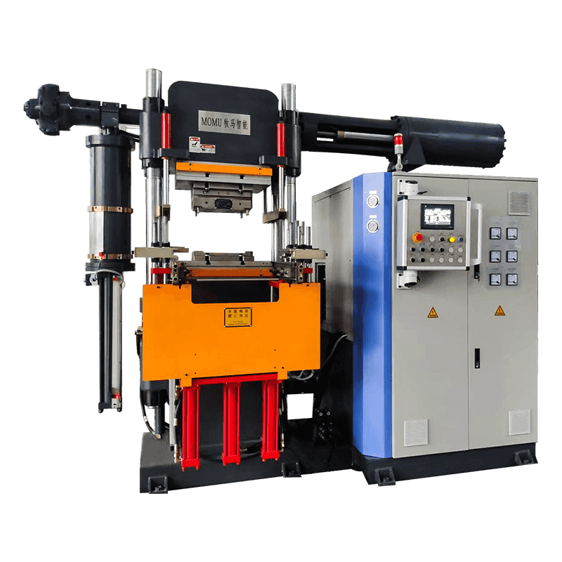
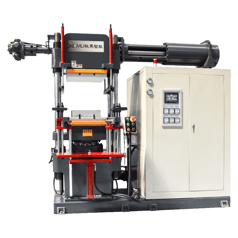
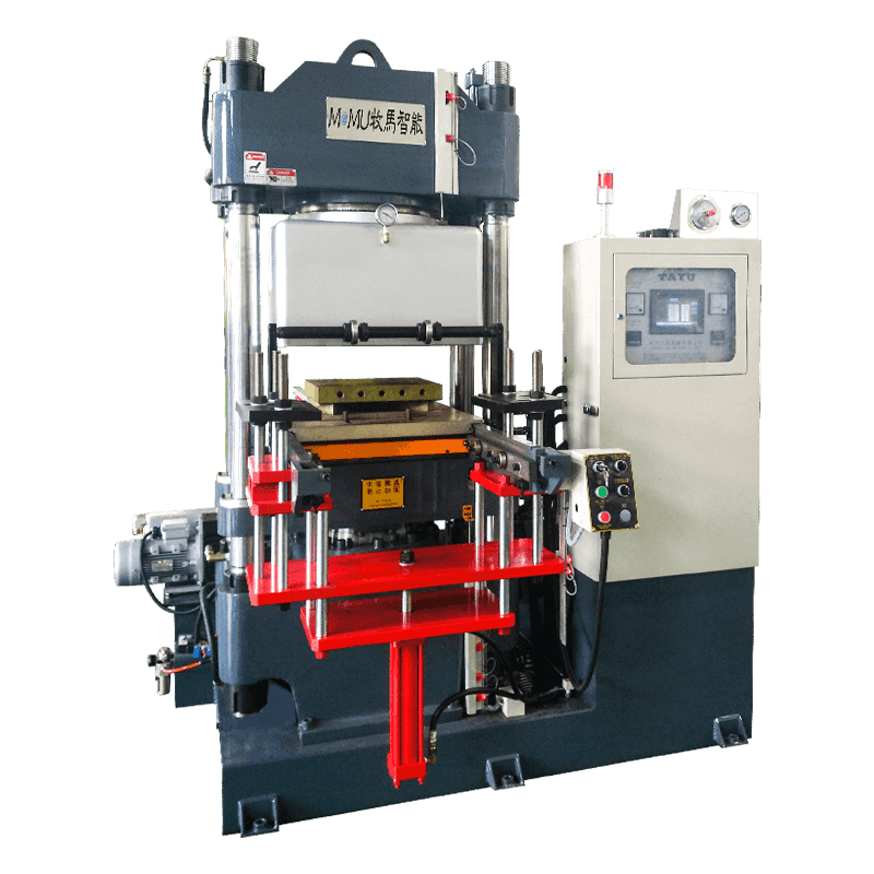
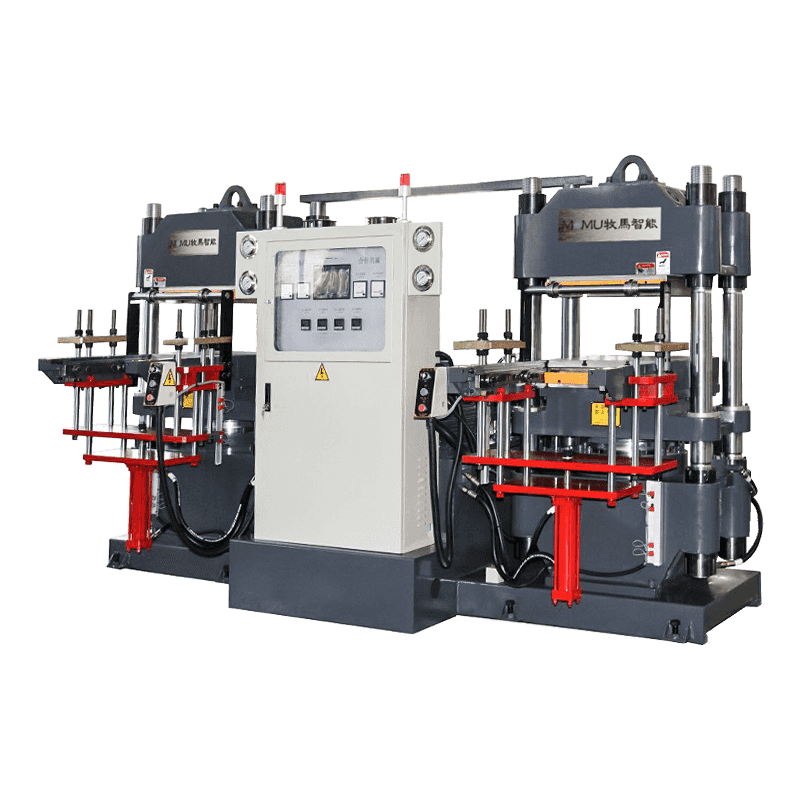
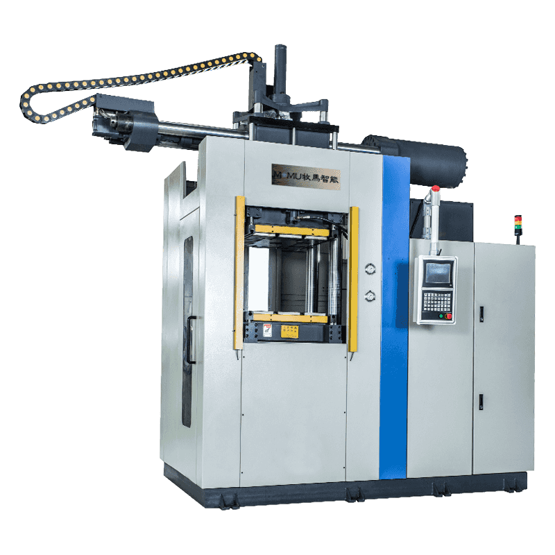 FIFO Rubber and Silicone Injection Molding MachineView it for a FIFO injection layout that pairs PLC three-stage control with capacities from 350 to 8000 cc.View Product →
Why Material Residence Time Matters
Rubber compounds are reactive. Even at the temperatures inside a plasticizing unit, a compound with a short scorch time is creeping toward cure, and the longer it stays hot — and the more unevenly that time is spread — the closer it comes to the point where it will no longer flow properly into the cavity.
That produces three familiar symptoms: pre-vulcanized particles that appear as hard specks and surface defects, viscosity that drifts from shot to shot and changes how runners and cavities fill, and shot weight that becomes harder to hold. The worst case is not continuous running but the unplanned stop. When a machine idles with compound in the barrel, the material nearest the hot zones ages fastest, and the first shots after a restart usually carry the evidence.
Benefits of a FIFO Injection Machine
- More consistent compound condition. Every portion sees a similar thermal history, so viscosity stays inside a narrower band.
- Less stagnation. Ordered flow leaves fewer corners where material can sit and cure.
- Stable shot preparation. With the feed rate and plasticizing path under control, the accumulated shot repeats cycle after cycle.
- More predictable injection pressure. Consistent compound behaves consistently, which turns pressure trends into a useful monitoring signal.
- Lower process-related scrap. Fewer scorched specks, short shots and flashes add up over a year of production.
FIFO Flow Compared with Uncontrolled Material Flow
| Process aspect | FIFO injection | Uncontrolled flow |
|---|---|---|
| Residence time | Similar for every portion of compound | Varies from portion to portion |
| Dead zones in the barrel | Few, by design | Common in corners and channels |
| Shot weight stability | Holds within a narrow band | Drifts across the shift |
| Scorch risk | Lower, because material does not wait | Higher, especially after stops |
| Restart after a stop | Predictable, with a short purge | Often needs longer purging and re-setting |
| Fit with automation | Good, the process repeats | Difficult, the process keeps moving |
Where FIFO Injection Fits Best
Ordered feeding pays off most where the compound is sensitive, the part is small or the tolerance is tight: precision silicone components, thin-wall parts, multi-cavity molds, sealing strip corners and hollow core insulators, where a scorched speck or a short shot cannot be polished out afterwards.
Insulator production is a good example. A hollow core insulator has a long, thin flow path, and the compound has to arrive in the cavity in uniform condition if the wall thickness is to stay even. We looked at this in more detail in a note on innovations in insulator injection molding technology, and we also build dedicated equipment for that kind of work.
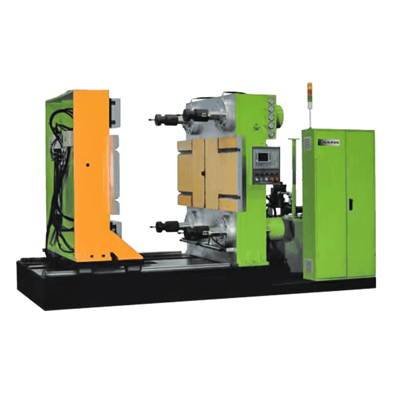
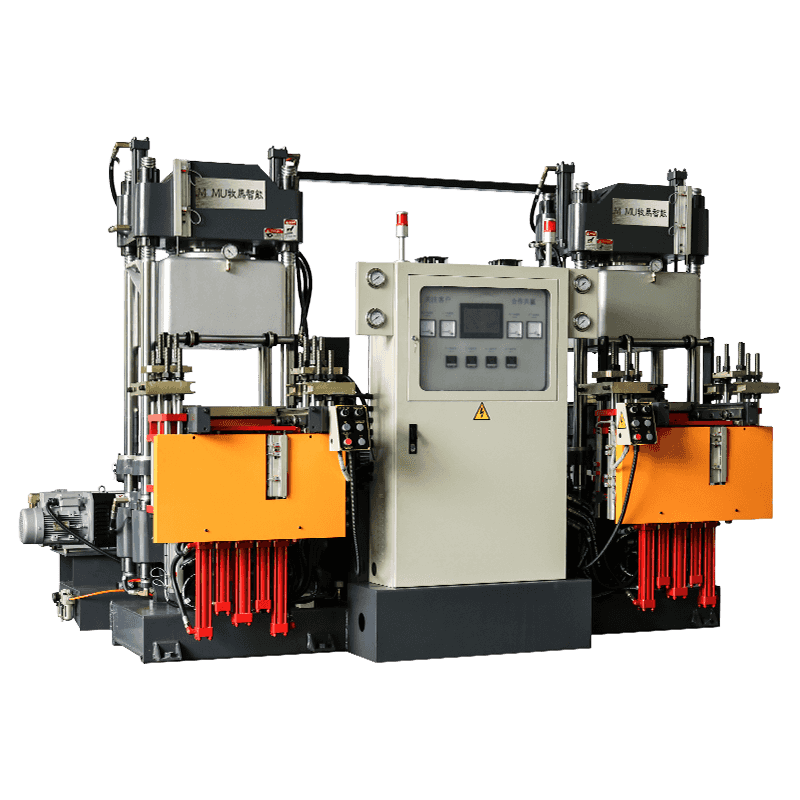
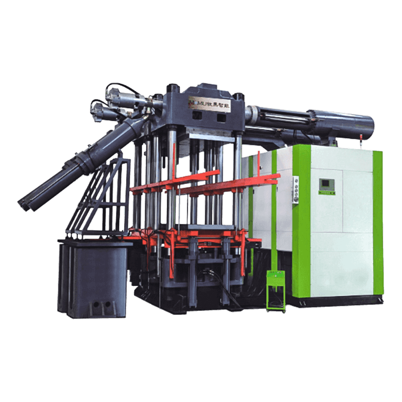 Special Silicone Insulator Injection Molding MachineBuilt for silicone insulators, its special plasticizing unit targets air inclusion and scorch, while rigid clamping helps limit flash on long molds.View Product →
Injection is only half of the story, of course. Once the blank is formed it still has to be vulcanized properly, and the choice between vacuum and other methods affects porosity and dimensional stability — a subject we covered in an article on the key differences between vacuum vulcanization and other vulcanization methods.
What a FIFO Feeding System Needs to Work Well
- Consistent strip dimensions. Width and thickness variation changes the volume fed each cycle before the plasticizing unit ever sees it.
- Controlled feed rate. The strip must advance in step with the shot rather than simply being pulled through.
- A clean feeding path. Dust, talc build-up and compound residue disturb gripping and cause slip.
- Stable gripping force. Too little and the strip slips; too much and it deforms or tears.
- Reliable sensors. Feed monitoring is what turns a mechanical arrangement into a repeatable process.
Common Feeding Problems and What They Look Like
- Short shots point to feed slip, a starved plasticizing unit or a shot size set too close to the machine's limit.
- Part weight variation usually follows an inconsistent feed rate or a residence time that changes during the shift.
- Flash and burn marks suggest viscosity has dropped or that partly cured compound is trapping air in the cavity.
- Surface inconsistency and cavity imbalance often trace back to scorched particles carried through from the barrel.
Choosing a FIFO Injection Machine
When customers ask us to size a machine, the conversation usually covers four things:
- shot size, and whether it sits comfortably inside the injection capacity rather than at the edge of it;
- the compound, its hardness and its scorch behaviour;
- part geometry, cavity count and mold layout;
- the machine layout that fits the cell — vertical, horizontal or angle type.
Layout matters more than it first appears. A vertical machine gives a small footprint and easy insert handling, while a horizontal one suits longer molds and automated take-out. If your part is short and the cycle is tight, the layout decision often shapes the rest of the project.
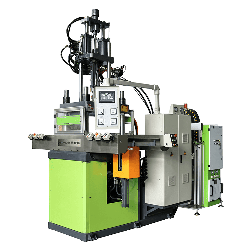
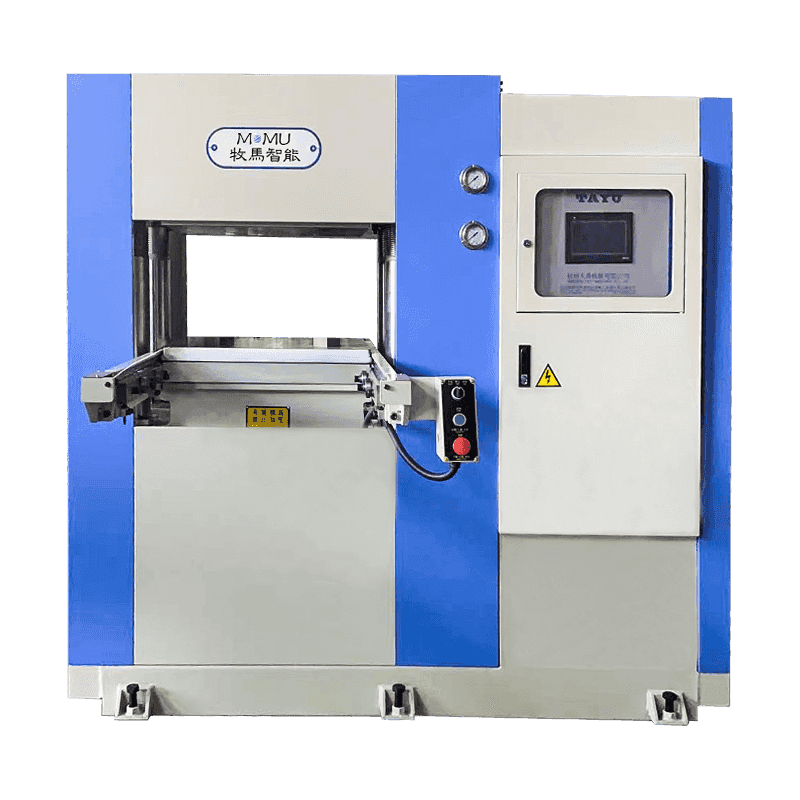
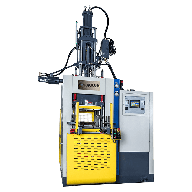 Vertical Rubber and Silicone Injection Molding MachineA vertical layout suits small footprints and insert handling, with high injection pressure for precision silicone parts and models from 100 to 550 tons.View Product →
Keeping a FIFO System Running Well
- Standardize the feed — same strip width, same storage conditions, same handling.
- Verify the processing window for each compound instead of copying settings between them.
- Watch injection pressure trends; a slow upward drift usually means something is changing in the feed or the plasticizing unit.
- Compare shot weight with part weight, so you know whether variation comes from the process or the mold.
- Limit unnecessary stops, and if a stop is unavoidable, purge before restarting.
- Inspect wear components such as rollers, seals and non-return elements on a schedule rather than after a failure.
Final Thoughts
A FIFO injection machine does not rely on a clever trick. It relies on keeping the compound moving in order, at a controlled rate, so that what enters the cavity is always material that has just been conditioned. That is why the principle keeps showing up in conversations about scorch, shot weight and scrap. If you are working through a feeding or residence-time problem on rubber or silicone, we are glad to talk through the details with you and help you find the layout and capacity that fit your parts.