Search
 English
 中文简体
 Español

Content
- 1 What First In, First Out Means Inside an Injection Unit
- 2 How the FIFO Injection Process Runs, Step by Step
- 3 Residence Time Is the Number That Really Matters
- 4 What You Notice on the Shop Floor
- 5 FIFO and Conventional Flow Side by Side
- 6 Where FIFO Machines Earn Their Keep
- 7 Specifying a FIFO Injection Machine
- 8 Running and Maintaining a FIFO Unit
- 9 Talking It Through With People Who Build the Machines
Rubber and silicone are forgiving materials right up until they are not. Compound that lingers too long in a barrel begins to cure before it ever reaches the mold, and the symptoms appear far from the cause: a short shot on cavity seven, a part that comes out two grams light, a flash line that shows up before lunch and disappears an hour later. A FIFO injection machine is built to take that particular uncertainty out of the process, and once a molding shop has run one, going back feels like a step backwards.
This article explains what first in, first out really means inside an injection unit, how the material path differs from a conventional machine, where the design pays off, and what to look at when you specify one.
What First In, First Out Means Inside an Injection Unit
FIFO describes a flow principle rather than an add-on feature. In a genuine first-in, first-out design, the compound that enters the plasticizing section first is also the compound that leaves the nozzle first, shot after shot, without overtaking or being overtaken by fresher material behind it.
On many conventional units the material path behaves more like a stirred tank than a queue. Compound can fold back on itself, linger in the clearance between screw flights and barrel wall, or settle in a slow-moving pocket near the front of the barrel while newer material streams past. The consequence is a wide spread of residence times inside a single shot: part of the dose may have been warm for two minutes, another part for twelve. The machine still injects, but it injects a mixture of fresh and elderly rubber, and the mold receives whatever that mixture happens to be.
A FIFO unit instead pushes compound forward as a plug. There is one route through the plasticizing zone, the geometry discourages dead corners, and material is displaced in the order it arrived. Fresh compound enters at the back, cured-ready compound waits at the front, and the boundary between them stays sharp.
How the FIFO Injection Process Runs, Step by Step
- Metered feeding. Compound strips, blanks or a continuous band enter the feed throat at a controlled rate, so the plasticizing zone is never starved and never overfed.
- Ordered plasticizing. The plastifying screw works the compound forward and heats it by shear and barrel temperature, without letting it recirculate back into the feed zone.
- Queue formation. Plasticized compound accumulates ahead of the injection piston in the exact sequence it was prepared, forming an ordered plug rather than a mixed reservoir.
- Injection. The piston drives the front of the queue through the nozzle first, so the freshest material stays behind while the fully conditioned material fills the cavity.
- Replenishment. Fresh compound follows immediately behind the previous shot, and the queue refills from the rear as it is consumed from the front.
Because the queue is orderly, the residence time of any given particle is predictable and very close to that of its neighbours. That single property is what everything else in a FIFO machine is built around.
Residence Time Is the Number That Really Matters
Rubber compounds react to time and temperature together. A formulation with a comfortable scorch safety at a five-minute residence time may be sitting on the edge at fifteen minutes, and compounds with short scorch windows, such as many peroxide-cured stocks and addition-cure silicones, are the first to complain. When residence time is uneven, viscosity varies from shot to shot, and viscosity variation shows up downstream as drifting shot weight, uneven cavity fill, flash, and surface defects that seem to come and go without explanation.
FIFO addresses the problem at the source. Every particle experiences nearly the same thermal history, so the cure state entering the mold is consistent. In practice this widens the processing window: longer cycles, larger shot volumes and higher cavity counts become viable, because the material at the front of the queue is always the material that was prepared first and is ready to inject.
What You Notice on the Shop Floor
The benefits of ordered flow tend to appear in ordinary production data rather than in demonstrations:
- Shot weight and part dimensions hold steadier across a shift, which simplifies quality checks.
- Scorch and pre-vulcanization defects drop, especially on long cycles and multi-cavity tools.
- Material and color changeovers clear faster, with less purging scrap before good parts return.
- Injection pressure behaves predictably, so cavity-to-cavity balance is easier to tune and keep.
- Automation is simpler to justify, because a repeatable shot is easier to hand over to a robot or an unattended run.
- Operators spend less time chasing intermittent faults and more time on setup and inspection.
FIFO and Conventional Flow Side by Side
The differences below are typical of the two design philosophies rather than rules about any single machine. Tooling, compound and cycle all shift the picture.
| Characteristic | Conventional flow | FIFO injection machine |
|---|---|---|
| Material path | Can loop and stall in low-flow areas | Single ordered route, plug flow |
| Residence time spread | Wide and hard to predict | Narrow and repeatable |
| Scorch risk | Higher on long cycles and large shot volumes | Lower, even at longer residence times |
| Shot weight stability | Drifts as the barrel fills and empties | Holds steady from shot to shot |
| Color and compound changeover | More purging scrap | Faster clean-out, less waste |
| Typical fit | Short cycles, tolerant parts | Precision parts, silicones, multi-cavity tools |
Where FIFO Machines Earn Their Keep
Ordered flow matters most where the compound is expensive, the cure window is narrow, or the tool has many cavities that must fill alike. That includes silicone insulators and hollow casings, oil seals, sealing strip corners, liquid silicone parts, and small precision components produced in high-cavity molds. Silicone work benefits twice over, since the material is both costly and sensitive to thermal history.
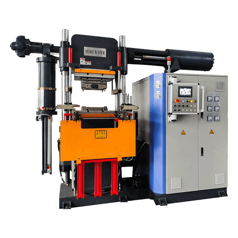
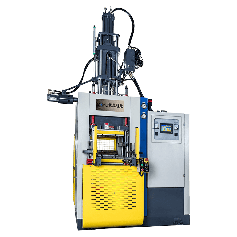
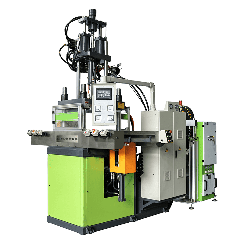
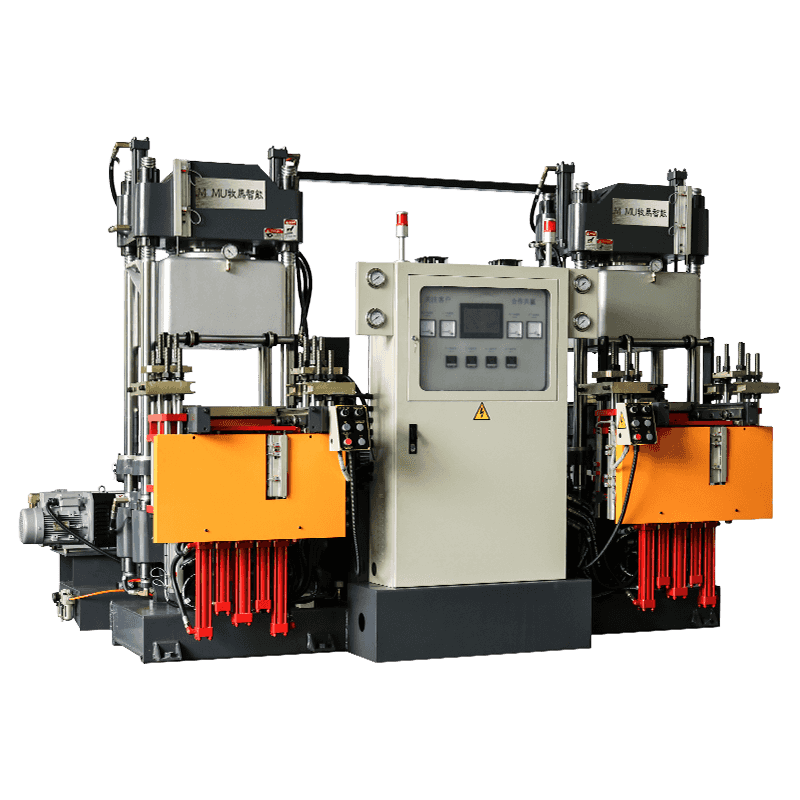
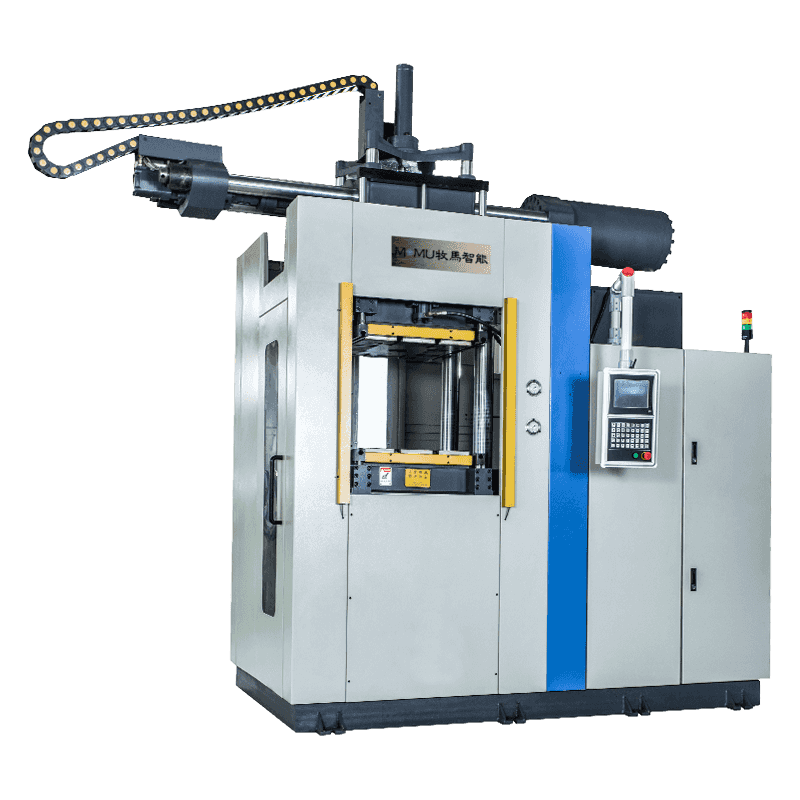 FIFO Rubber and Silicone Injection Molding MachineFor expensive compounds and multi-cavity silicone work, this FIFO injection machine offers PLC three-stage control and models from 100 to 550 tons.View Product →
It is worth saying plainly that FIFO is not the answer to every job. Very short cycles on thick, forgiving compounds may gain little, and simple compression or vacuum vulcanizing routes can still be the economical choice. When a project involves long residence times or tight dimensional tolerances, though, the ordered path usually pays for itself in yield. Our article on injection molding technology for insulators looks at how these demands play out in one specific industry.
Specifying a FIFO Injection Machine
Once the feeding principle is settled, the specification work is mostly arithmetic and a few good questions. Match the shot volume to the cured part weight plus runner, allowing a sensible margin; check clamp force against the projected area and cavity count; and confirm that the plasticizing capacity supports the cycle time you actually intend to run, not the one in the brochure.
- Maximum shot volume against part weight, runner weight and number of cavities.
- Clamp force and platen size, measured against the mold you plan to use.
- Compound hardness and form: strip, blank or continuous band, since feeding geometry follows from it.
- Temperature control zones and how precisely the barrel profile can be held.
- Injection pressure and speed range, with room for the adjustments real production always demands.
- Machine layout, control platform, spare parts availability and local service response.
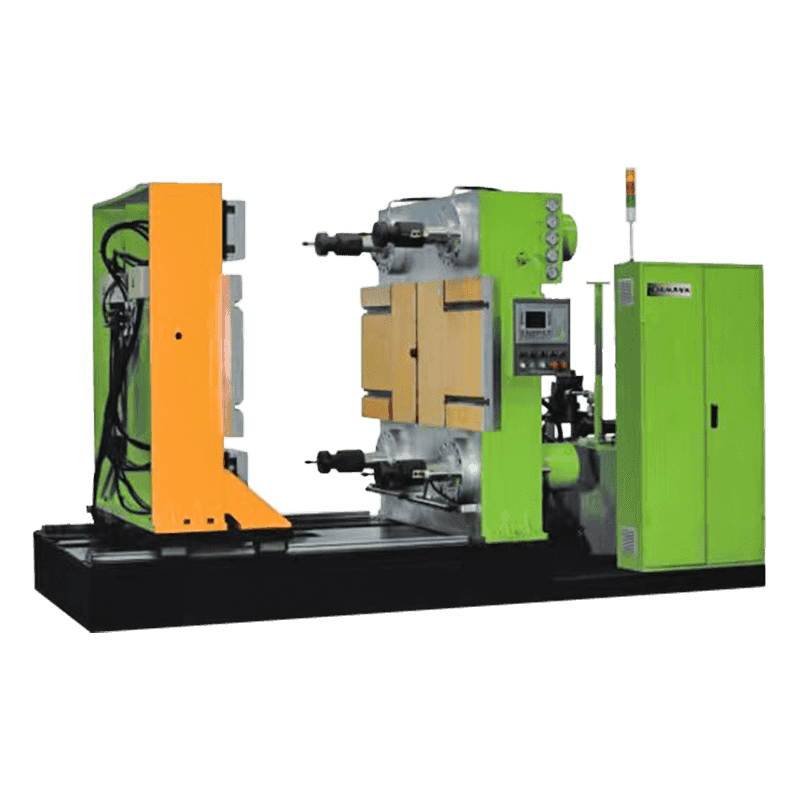
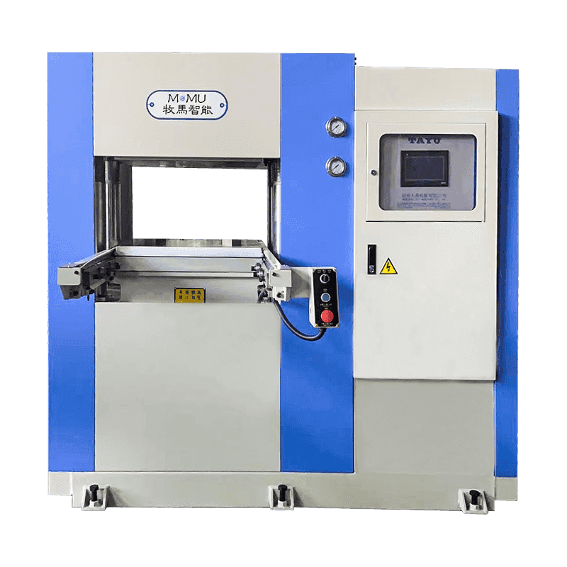
Layout is a separate decision from the feeding principle. A 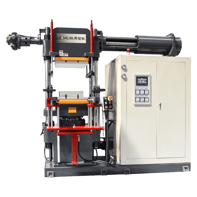 Horizontal Rubber and Silicone Injection Molding MachineA fully automatic horizontal model with FIFO injection and cold runner design, suited to precision rubber and silicone production from 100 to 330 tons.View Product → horizontal machine suits most free-standing molds and integrates easily with take-out robots, while vertical versions make more sense when inserts have to be loaded by hand.
Running and Maintaining a FIFO Unit
The design rewards a little discipline. Standardize how compound is fed and how long it waits on the feed table; verify the processing window for each compound rather than transferring settings from another machine; watch injection pressure trends for slow drift; and compare shot weight against part weight regularly so small changes are caught early. Avoid unnecessary idle time with a full barrel, keep the feed path clean, and inspect wear items such as the screw tip, check valve and nozzle on a fixed schedule. Record the settings that produced good parts, so a repeat order starts from a known point instead of a guess.
Talking It Through With People Who Build the Machines
We have been building rubber and silicone molding equipment since 2016, and over that time the questions that come up have changed very little: will the machine hold my tolerance, how long does a changeover take, and who answers the phone when something runs badly at two in the morning. The answers usually come down to matching the right configuration to the job, which is why we would rather look at your part drawing and cycle requirement first and recommend a machine second.
If you are weighing up a FIFO design against another configuration, send us the details of the part, the compound and the tool, and we will tell you honestly which route fits. You can browse the wider range on our product overview page as a starting point.